Thermoelectrics
Thermoelectric Engineering
Thermoelectric Power Generation
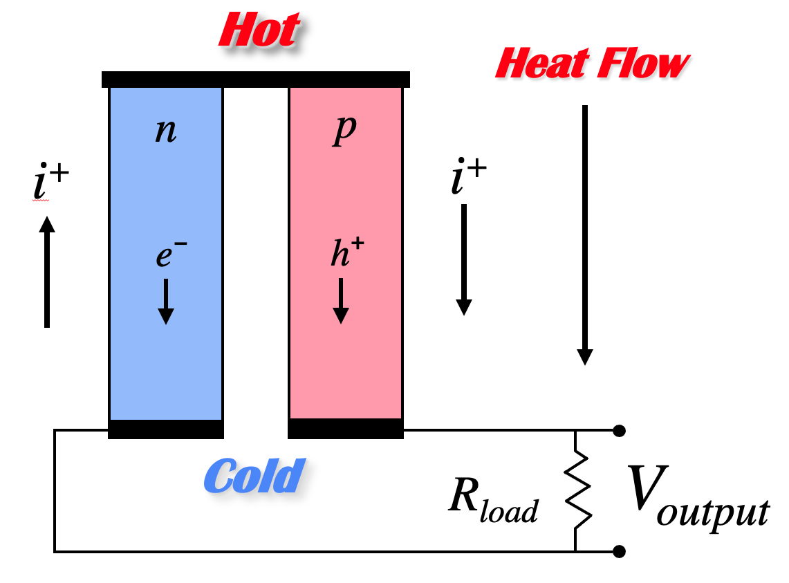
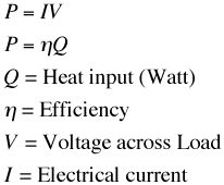
If the hot ends of the n-type and p-type material are electrically connected, and a load connected across the cold ends, the voltage produced by the Seebeck effect will cause current to flow through the load, generating electrical power. The electrical power produced is the product of the voltage and electrical current across the load. The temperature difference provides the voltage but it is the heat flow which enables the current.
A thermoelectric generator behaves much like an ideal voltage source with an internal resistance due largely to the resistance of the thermoelectric materials themselves. The voltage at the load is reduced from the open circuit voltage by the Ohm's law (V = IR) voltage drop due to this internal resistance. Maximum efficiency is reached when the load and internal resistances are nearly equal because this is close to the maximum power achieved from load matching.
The resistance of the thermoelectric elements depend on the electrical resistivity as well as the length and cross sectional area.
Just as the power in a resistor is V2/R the power produced in a thermoelectric generator depends on the square of the voltage (Seebeck coefficient and temperature difference) divided by the resistivity. Notice also that the power per area can be arbitrarily adjusted with l (length).
The efficiency of a generator depends not just on the power produced but also how much heat is provided at the hot end. The heat input is needed for the thermoelectric process (Peltier effect) as well as normal thermal conduction (Fourier's law) and is offset by the Joule heating in the device. The Fourier's law thermal conduction of the thermoelectric materials add a thermal path from hot to cold that consumes some heat and reduces the efficiency.
It can be shown that the maximum efficiency of a thermoelectric material depends on two terms. The first is the Carnot efficiency, for all heat engines can not exceed Carnot efficiency. The second is a term that depends on the thermoelectric properties, Seebeck coefficient, electrical resistivity and thermal conductivity. These material properties all appear together and thus form a new material property which we call zT, the Thermoelectric Figure of Merit. For small temperature difference this efficiency is given by:

Notice also that the extensive geometric parameters, length and area have dropped out of this expression for maximum efficiency. In a real generator with large temperature difference other methods and approximations are frequently used to calculate performance.
Another material property that becomes important when different materials or large temperature differences are used, is the thermoelectric compatibility factor s. For power generation, the compatibility factor should not change by more than a factor of two from the hot to the cold end of a thermoelectric element.
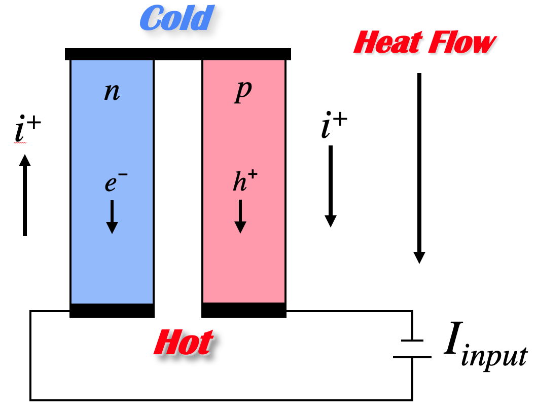
Peltier Cooling
If instead of having the heat flow drive the charge flow, we use an external electric potential to drive the heat carrying charges, then we can force heat to flow from one end to the other. The coefficient of performance and the maximum temperature drop that can be achieved is again related to the efficiency of the thermoelectric materials through the thermoelectric figure of merit zT.
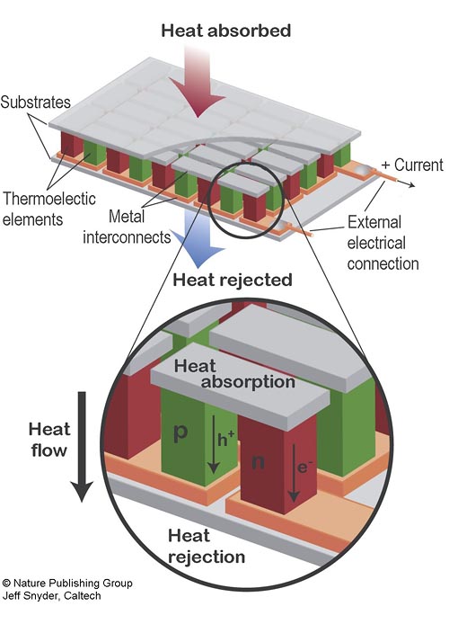
Thermoelectric Devices
Thermoelectric devices are made from thermoelectric modules. A thermoelectric module is a array of thermocouples connected electrically in series but thermally in parallel.
Many couples are used (in both power generation and cooling) becuause the voltage drop across one couple is only on the order of millivolts. Connecting many in series brings the voltage closer to that found in typical DC power souces. The effective Seebeck voltage (not including the Ohmic, IR voltage drop) of the device, S is derived from the Seebeck coefficient of the n-type and p-type elements and the number of couples, n and can be approximated as
The electrical resistance of the device depends not only on the electrical resistance of the thermoelectric materials but also the electrical resistnace of the metal interconnects and the contact resistance between the interconnects and the thermoelectric materials. All of these contributions are temperature dependent making the exact computation of the resistance complex. The device resistance, R, can be approximated
assuming temperature independent properties. Here Rl is the interconnect and contact resistance (loss) per couple, l is the length (height) and A is the cross-sectional area of the thermoelectric elements.
Similar to the electrical resistance, the total thermal conductance of the device can be approximated by
where Kl is the parallel thermal loss per couples associated with gas conduction, radiation, or other losses.
With these values the net heat abosorbed or produced can be estimated from the sum of the Peltier, Fourier, and Joule heat terms.
![]()
When operating as a cooler the best performance is achieved when then the current is approximately equal to Imax . When there is no heat load (Q=0) the temperature difference is ΔTmax. When there is no ΔT, the maximum heat pumping is Qmax.
For these approximations, the device figure of merit for cooling, ZT is analogous to the material figure of merit zT.
The performance of a TE cooler can then be written in the Generalized Cooling Equation which can be used for Q and COP vs I at constant ∆T.

In a thermoelectric generator, the efficiency is often approximated with
where ZT is thermoelectric figure of merit for the generator. Again ZT is related to and under certain approximations equal to the material figure of merit zT.
For the exact calculation of device ZT that accounts for temperature dependent thermoelectric properties including the compatibility effect see device ZT page.
Reference: Heikes, R. R. & Ure, R. W. Thermoelectricity: Science and Engineering (Interscience, New York, 1961).
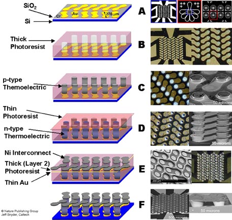
Micro Thermoelectric Devices
The ability to fabricate small semiconducting thermoelements has enabled the production of exceedingly small thermoelectric genetarors and Peltier coolers. The smaller devices operate with mich higher heat fluxes (heat/area) which can benefit certain applications. Various thin film techniques have been utilized to produce small thermoelectric devices including electrochemical MEMS which is described in the MicroDevice page.
Segmented Generators
To achieve high efficiency, both large temperature differences and high figure of merit materials are desired. Since the material thermoelectric properties (Seebeck coefficient, electrical resistivity, thermal conductivity) vary with temperature it is not desirable or even possible to use the same material throughout an entire, large temperature drop. Ideally, different materials can be segmented together such that a material with high efficiency at high temperature is segmented with a different material with high efficiency at low temperature. In this way both materials are operating only in their most efficient temperature range.
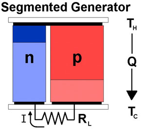
Thermoelectric Generator Segmented with two different n-type
materials and two different p-type materials
Segmented Thermoelectric coolers can, in principle, have profound effects on performance. With extreme segmenting, such that thermoelectric compatiblity is maintained, the thermoelectric cooler utilizes the Thomson effect to work like a Peltier cooler with many stages increasing the maximum ∆T that can be achieved.
see: G. Jeffrey Snyder, E. S. Toberer, Raghav Khanna, Wolfgang Seifert, “Improved Thermoelectric Cooling Based on the Thomson Effect” Physical Review B 86, 045202 (2012).
Thermoelectric Compatibility
Only compatible materials can be used in a segmented genertor. One aspect is thermoelectric compatibility which is due to the requirement that the heat and electric charge must flow through the same materials connected in series.
The Current-Voltage-Power characteristics of a thermoelectric generator can be explained by a reduction in voltage with applied current due to the internal resistance of the thermoelectric material. At zero current the (open circuit) voltage is high but no power is produced. As the current is increased, the power increases to a maximum. At high currents, the voltage drops to zero or below and the power produced drops to zero or becomes negative (consuming instead of producing power).
Typical current-voltage and power curve for a Thermoelectric Generator
On the microscopic scale, a similar relationship holds where the efficiency (like Power above) varies with the relative current density u.
![]()
The maximum efficiency (determined by z) is only achieved when the
relative current density u, is equal to the compatibility factor s.
In an efficient generator the relative current density is roughly a constant throughout a segmented element (typically u changes by less than 20%).
Materials Selection
Thus the goal is to select high figure of merit materials that have similar compatibility factors. If the compatibility factors differ by a factor of two or more, a given u can not be suitable for both materials and segmentation will not be efficient. Compatibility is most important for segmented generators because the thermoelectric material properties may change dramatically from one segment to another.
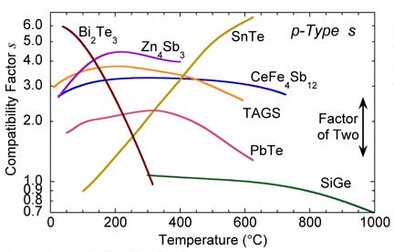
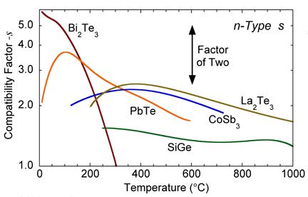
From the plot of s vs. temperature for various materials, one can see that SiGe is not suited for segmentation with most of the other high zT materials. In addition, the compatibility factor can be used to explain why segmentation of TAGS with PbTe or SnTe near 600 C produces little increase in efficiency.
Segmented vs. Cascaded Generator
The compatibility issue can be avoided by cascading a thermoelectric generator instead of segmenting. In a cascaded system, there are (in principle) independent electrical circuits for each stage. Independent electrical current allows independent values of the relative current density u, in each stage. In this way, the optimal u can be used for each stage.
In practice, it is best not to connect the high temperature stages directly to the load. Such connectors would be inefficient because if they had low electrical resistance they will conduct heat away from the hot side (due to Wiedeman Franz law); if they have high electrical resistance, there will be additional Joule losses. To avoid such losses the electrical current should pass from the high temperature stage to the load by going through the thermoelectric elements of the low temperature stage.
Two Stage Cascaded Thermoelectric Generator
References
G. Jeffrey Snyder and Eric S. Toberer "Complex Thermoelectric Materials" Nature Materials 7, 105-114 (2008).
Snyder, G. J. "Thermoelectric Power Generation: Efficiency and Compatibility" Chapter 9, CRC Handbook on Thermoelectrics. (2005)
Snyder, G. J. "Application of the Compatibility Factor to the Design of Segmented and Cascaded Thermoelectric Generators" Appl. Phys. Lett. Vol 84, p. 2436 (2004)
G. Jeffrey Snyder, Tristan Ursell. "Thermoelectric efficiency and compatibility" Physical Review Letters, Vol 91 p. 148301 (2003)
More on Segmented Generators: Technology Development at NASA-JPL
The MHW/GPHS RTG (used on Gallileo and Cassini) uses the thermocouples shown below which are segmented with two slightly different SiGe compositions.
Segmented Unicouple Technology
Segmented New Materials Unicouple
Adhesion Layer / Diffusion Barrier
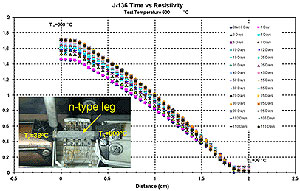
Electrical Contact Resistance Testing
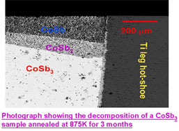
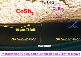
Surface Sublimation and Preventitive Coatings
Unicouple Testing
Applications
975K-375K Segmented Unicouple Development Path